Entradas

Mostrando las entradas de julio, 2021

▷ SOLUCIÓN LECCIÓN FUNDAMENTOS DE ELECTRICIDAD Y SISTEMAS DIGITALES, 2do Parcial (2021 PAO1) C3
Imagen
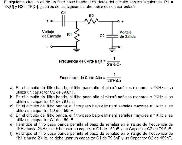
⭐⭐⭐⭐⭐ SOLUCIÓN LECCIÓN FUNDAMENTOS DE ELECTRICIDAD Y SISTEMAS DIGITALES, 2do Parcial (2021 PAO1) C3 from Victor Asanza ➡️  #DigitalSystems #DigitalElectronic #DigitalCircuits #HDL #VHDL #FPGA ⭐  https://github.com/vasanza/MSI-VHDL Leer temas relacionados ✅  2020 PAO2: Examen de Mejoramiento ✅  2020 PAO2: Examen 2da Evaluación ✅  2020 PAO2: 3ra Lección C4 ✅  2020 PAO2: 2da Lección C3-4 ✅  2020 PAO1: Examen de Mejoramiento ✅  2020 PAO1: Examen 2da Evaluación ✅  2020 PAO1: 3ra Lección C4 C ✅  2020 PAO1: 3ra Lección C4 B ✅  2020 PAO1: 3ra Lección C4 A ✅  2020 PAO1: 2da Lección C3 C ✅  2020 PAO1: 2da Lección C3 B ✅  2020 PAO1: 2da Lección C3 A
▷ SOLUCIÓN EVALUACIÓN SISTEMAS DIGITALES 1, 1er Parcial (2021 PAO1)

Imagen
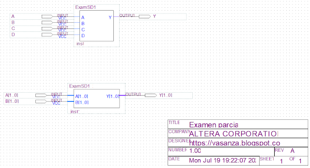
⭐⭐⭐⭐⭐ SOLUCIÓN EVALUACIÓN SISTEMAS DIGITALES 1, 1er Parcial (2021 PAO1) from Victor Asanza   ➡️  #DigitalSystems #DigitalElectronic #DigitalCircuits #HDL #VHDL #FPGA ⭐  https://github.com/vasanza/MSI-VHDL ✅ Problema #1 (x%) . El siguiente es un Sistema Digital que tiene las señales ‘A’,’ B’, ‘C’ y ‘D’ como entradas de un bit; por otro lado, la señal ‘Y’ es una salida de un bit tal como se muestra en la siguiente imagen: El comportamiento de la señal de salida ‘Y’ en función de las señales de entrada, es descrito con el siguiente código VHDL: ⭐  Código GitHub: https://github.com/vasanza/MSI-VHDL/blob/2021PAO1/ExamenParcial/ExamSD1_1.vhd Realizar los siguientes desarrollos: a) Usando mapas de karnaught y agrupamiento de minterms (SOP), simplificar la expresión booleana hasta obtener su minima expresión (x/2 %). b) Utilizando puertas lógicas, graficar el circuito que represente a la ecuación simplificada en el literal anterior (x/2 %). Resolución: a) b) ✅ ...

▷ Maximum number finder and repetition counter (VHDL Functional Partition)

Imagen
 ⭐⭐⭐⭐⭐ Maximum number finder and repetition counter (VHDL Functional Partition) ➡️  #DigitalSystems #DigitalElectronic #DigitalCircuits #HDL #VHDL #FPGA In this functional partition example, it performs the following tasks: Allows entry of up to 255 4-bit numbers Then search for the highest number and indicate the number of times it is repeated The software used was Quartus Prime 19.1 Repository with VHDL codes: https://github.com/vasanza/DigitalSystems/tree/2021PAO1/Ejemplo3_BuscadorMaxRep Functional Partition PDF: https://github.com/vasanza/DigitalSystems/blob/2021PAO1/Ejemplo3_BuscadorMaxRep/notasclase.pdf Read related topics ✅ #FPGA projects for Engineering Students Phrases recognition with Machine Learning #ML (InnovateFPGA) Example: Access control system (2) Example: Access control system (1) ✅ 2020 Paper: Monitoring of system memory usage embedded in #FPGA ✅ 2020 Paper: Implementation of a Classification System of #EEG Signals Based on #FPGA ✅ 2020 Paper: Behavioral Sig...

▷ TSC-Lab Open Hardware Certification

Imagen
  ⭐⭐⭐⭐⭐ TSC-Lab Open Hardware Certification ☑️ #TSCLab #TSC_Lab #TSC Open hardware Certification: https://certification.oshwa.org/ec000003.html Open Source Licenses: Blog: https://tsc-lab.blogspot.com/ VIEW DOCUMENTATION: https://github.com/vasanza/TSC-Lab Data Sheet Citations: Víctor Asanza, Kevin Chica-Orellana, Jonathan Cagua, Douglas Plaza, César Martín, Diego Hernan Peluffo-Ordóñez. (2021). Temperature and Speed Control Lab (TSC-Lab). IEEE Dataport. https://dx.doi.org/10.21227/8cty-6069 TSC-Lab modular design, based on Top - Down hardware design method: Temperature and speed control electronics: Controller based on ESP32: Peripherals and indicators for the user: Power supply: PCB (Top Layer): PCB (Bottom Layer): 3D printed parts:  View Documentation: https://github.com/vasanza/TSC-Lab Download TSC-Lab design document: Read related topics ✅  Ensemble de #PCBs - Electrograma #EMG / #ECG ✅  Ensemble de #PCBs - Energy Consumption ✅  Manufactura d...

▷ SOLUCIÓN EVALUACIÓN FUNDAMENTOS DE ELECTRICIDAD Y SISTEMAS DIGITALES, 1er Parcial (2021 PAO1)

Imagen
⭐⭐⭐⭐⭐ SOLUCIÓN EVALUACIÓN FUNDAMENTOS DE ELECTRICIDAD Y SISTEMAS DIGITALES, 1er Parcial (2021 PAO1) from Victor Asanza   ✅  Problema #8: (15%) Dado el siguiente circuito basado en un transistor NPN, Realizar los pasos que se indican en el siguiente diagrama de flujo y determinar la región de operación del transistor (justificar su respuesta). Realizar el mismo procedimiento para cuando el interruptor del circuito está en la opción A y B. Resolución:   ✅ Problema #1: (10%) Dadas las siguientes simbologías de componentes electrónicos, seleccionar el literal que tenga los nombres correctos de cada símbolo presentado: a) 1) Resistencia; 2) Fuente de alimentación; 3) Diodo de Zener; 4) Interruptor; 5) Transformador; 6) Capacitor Electrolítico; 7) Diodo Led; 8) Óhmetro; b) 1) Capacitor Electrolítico; 2) Fuente de alimentación; 3) Óhmetro; 4) Interruptor; 5) Transformador; 6) Resistencia; 7) Diodo Led; 8) Diodo de Zener; c) 1) Resistencia; 2) Fuente de alimentación;...